r/ECE • • Jul 08 '26

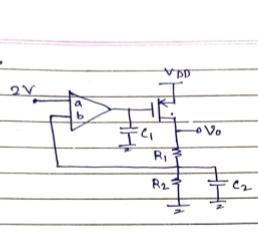
HOMEWORK (GOOD) Poles of this circuit?
Post image
73 Upvotes

This is one of the questions my senior came across in his interview.

Question was to find the pole of the circuits. In the document, my senior has remarked apparently there are 2 poles, and even I seem to think this but not getting a concrete way to prove it.

Moreover he was also asked about the locations of the poles.

Now I beleive one of the pole is (-1/R2C2)?

But is that right? If yes I don't think at that frequency the Vo saturates(which I feel is the requirement for pole)

Overall any suggestions to better solve such questions.

Note: it's expected that the answer is more intuitive rather than rigourous KCL and KVL

Edit: forgot to mention. Circuit is in negative feedback as in b is positive terminal and a is negative terminal of the opamp
r/ECE • • 21d ago

HOMEWORK (GOOD) Can someone help me with a simulation on Ltspice pls🥹

Thumbnail gallery
35 Upvotes

I tried simulating a circuit however I'm not getting the expected output. I would be really grateful if someone helps me simulate that plss. This is the circuit and 2nd pic shows the connection i tried to make. I also tried adding a buffer circuit in between but that didn't work as well.

r/ECE • • 3d ago

HOMEWORK (GOOD) Help with Thevenin equivalent circuits

Post image
41 Upvotes

In advance, I appreciate the help. I know this sub has a "do your own homework" attitude, but I've been staring at this problem for hours and can't figure out how to proceed. I understand TEC circuits pretty well, and had minimal issues with every other problem, but this specific one has stumped me. I've reread my chapter and watched TEC lessons on Youtube, but can't find anything that fits this specific example.

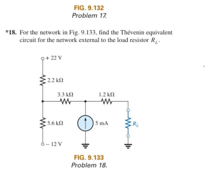
I've got half of this solved. Finding the Thevenin Resistance is simple enough, I shorted the Voltage Sources and opened the Current Source. 1200 +3300 + ((2200*5600)/(2200+5600)) is ~6080 ohms.

Where I'm running into an issue is finding the Thevenin Voltage. If the Load Resistor is opened, then it seems to me that the entire circuit is open. If the circuit is open, then the current source has nowhere to flow, and I can't find the solution. I would convert the current source to a voltage source if I could, but I don't think that can be done, because there is no parallel resistor.

The best solution I've come up with is to find the voltage at the junction between the two voltage sources and their resistors, while treating the current source as non existent because it doesn't have anywhere to flow to. However when testing this result (12.41 V) in a simulator it doesn't seem to work. What am I doing wrong?

Edit: Solved, Thank you everyone for your help. If anyone is having trouble with a problem like this themselves, I worked it out and posted the steps in the comments below.

r/ECE • • Sep 08 '26

HOMEWORK (GOOD) Question: why does transconductance gm of a MOSFET not vary with changing Vgs, ideally?

9 Upvotes
The circuit in question

First-time poster here, Idk if I'm breaking any rules or something
So this question made me realize that I really don't get gm and small-signal analysis. The question says to verify that gm = K(Vin - Vout - Vt) (Vin and Vout being the operating point).

This result is obtainable by taking the partial derivative of Id with respect to Vgs as per the formula, but looking at the way we obtain that derivative in the first place, I don't see why we didn't consider v_OUT as another independent variable contributing to v_gs (since v_gs = v_in - v_out)? Basically if v_in changes, so will v_gs, which will induce a current change, and that would affect v_out, which would change v_gs again?

So I expected that I'd have to differentiate both v_in and v_out with respect to v_in in the current expression k(v_in - v_out - v_t)2/2 instead of taking the partial derivative, which expanded into some crazy quadratic in terms of v_out which I solved and differentiated, but obviously it was entirely wrong. And I have gone through a bunch of explanations online but still haven't the foggiest as to this entire thing. Can someone here explain how we can seemingly ignore v_gs's dependence on v_out? Thanks in advance

r/ECE • • 27d ago

HOMEWORK (GOOD) Question about applying KCL: are I₃ and I₄ the same current in this circuit?

Post image
5 Upvotes

I'm a first-year ECE student doing a KCL laboratory experiment, and I'm confused about how KCL should be applied to this circuit.

At the central junction, (I_1) enters while (I_2) and (I_3) leave. So I believe:

[ I_1 = I_2 + I_3 ]

On the right side, (I_3) and (I_4) are measured at different points along the same continuous branch. There is no junction between them, so I believe:

[ I_3 = I_4 ]

Therefore, I don't think it would be correct to write:

[ I_1 = I_2 + I_3 + I_4 ]

because that seems to count the same branch current twice.

For example, one of our measurements at 2 V was:

  • (I_1 = 1.2,A)
  • (I_2 = 0.7,A)
  • (I_3 = 0.5,A)
  • (I_4 = 0.5,A)

This gives:

[ I_2 + I_3 = 0.7 + 0.5 = 1.2,A ]

and:

[ I_3 = I_4 = 0.5,A ]

So both relationships appear to be satisfied.

Am I applying KCL correctly here, or am I misunderstanding the circuit?

r/ECE • • Sep 05 '26

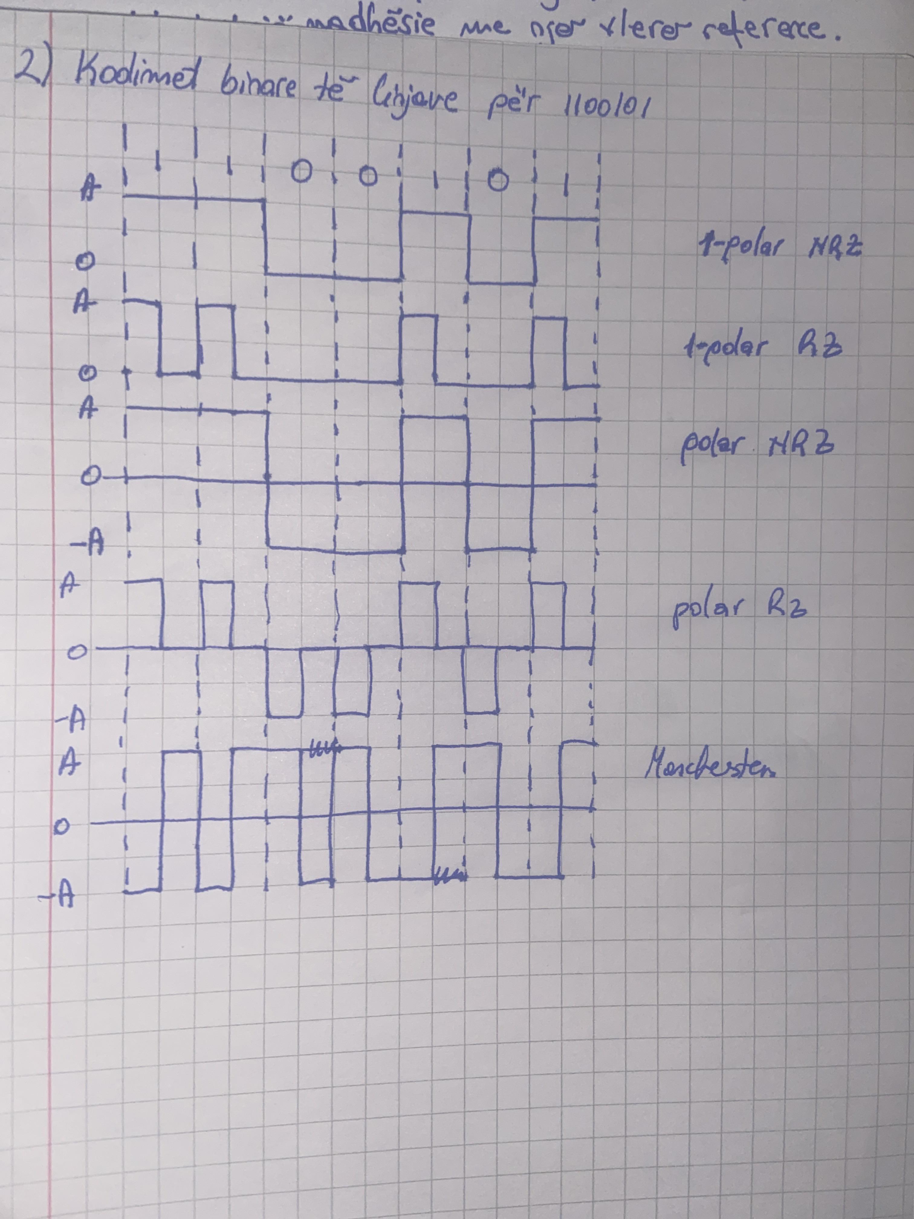
HOMEWORK (GOOD) Line coding of 1100101

Post image
21 Upvotes

Hi guys , can u help me check if I solved this exercise right?

r/ECE • • Jun 01 '26

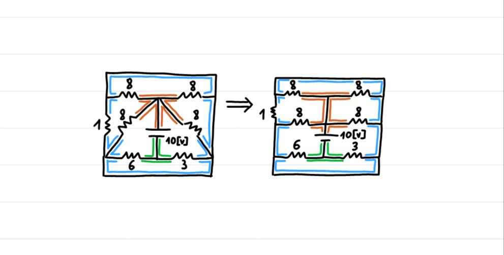
HOMEWORK (GOOD) Can someone explain to me how to connect an equivalent resistor to the rest of the circle? For example, in this problem, the two middle-top 8-ohm resistors are in parallel, but how do I connect their equivalent resistance to the rest of the circle?

Post image
6 Upvotes

Is there a rule on how to connect equivalent resistor to a circle? (I am not asking to solve the problem for me)

r/ECE • • Sep 17 '25

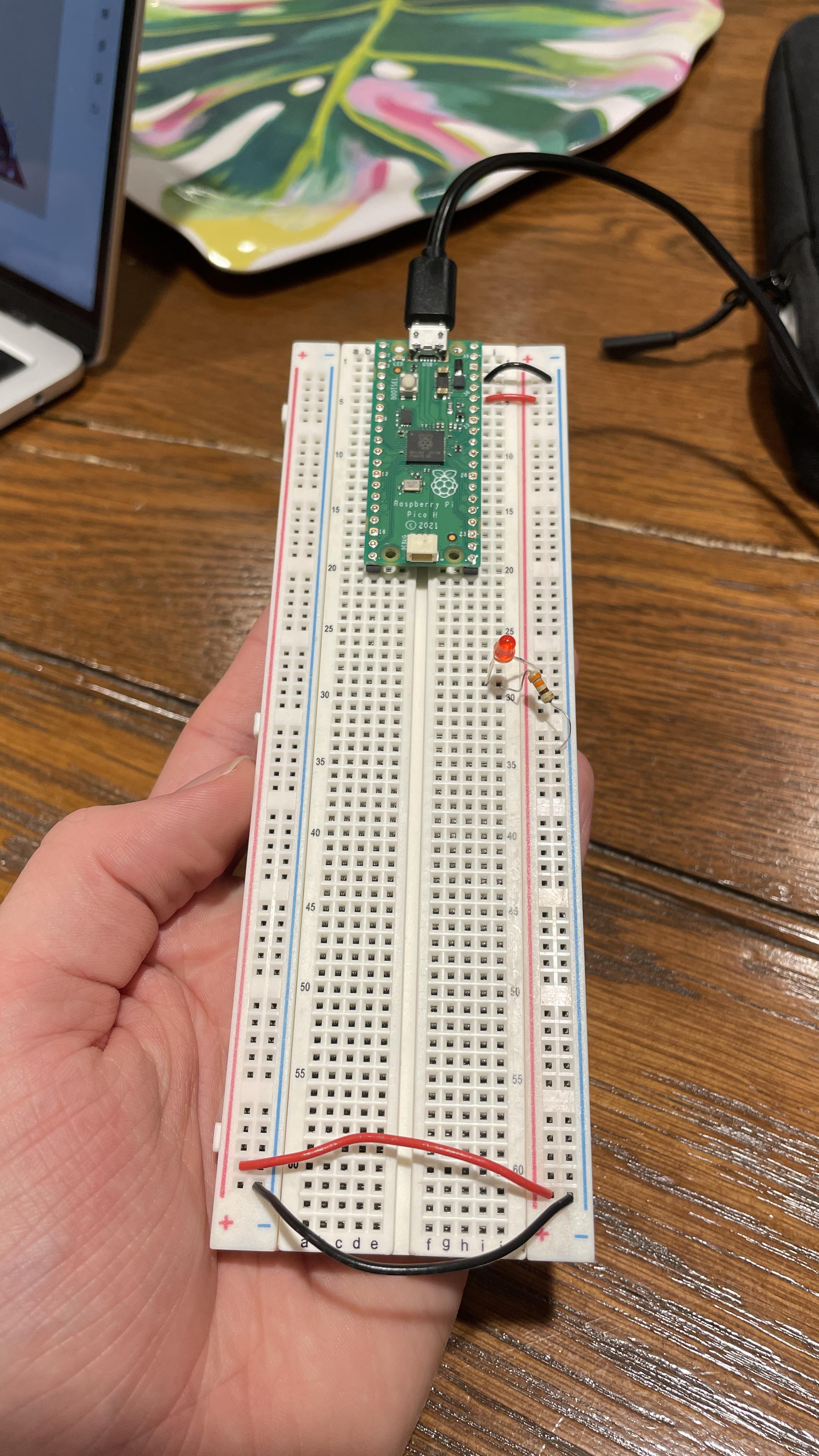
HOMEWORK (GOOD) Problem w/ Breadboard? Everything should be correct but no power.

Post image
45 Upvotes

Can someone help me with this? Do I have a short or something wrong with this. Its connected to power, the LED is connected to positive on the long side and the resistor on the short side. The LED isn't turning on though, so is it possible that something is just faulty?

r/ECE • • Jun 16 '26

HOMEWORK (GOOD) Why do we assume s=jw ? This is bugging me for a while and I can't understand it 😐

Thumbnail
0 Upvotes

r/ECE • • Jul 10 '26

HOMEWORK (GOOD) Silvaco ATLAS: How should OFF-state gate leakage (Ig_off) be correctly extracted for a HfO₂ gate dielectric MOSFET?

1 Upvotes

Hi everyone,

I'm working on a TCAD simulation of a 50 nm planar Si nMOSFET with a 2 nm HfO₂ gate dielectric in Silvaco ATLAS as part of my thesis.

My objective is to obtain physically meaningful values for:

  • OFF-state drain leakage current (I_off)
  • OFF-state gate leakage current (Ig_off)
  • ON-state drain current (I_on)
  • ON-state gate current (Ig_on)

The drain current values appear reasonable, but I'm uncertain about the correct methodology for obtaining Ig_off.

When the device is biased in the OFF state (VGS = 0 V, VDS = 1 V), extracting the gate terminal current sometimes gives a value that closely follows the drain leakage current, sometimes becomes extremely small, and in some cases is essentially zero. I'm not sure whether this represents the actual gate oxide tunneling current or is simply a consequence of terminal current accounting.

My question is:

  • What is the recommended or standard way to obtain OFF-state gate leakage (Ig_off) in Silvaco ATLAS?
  • Should it be extracted directly from the gate terminal current, or from the integrated tunneling current density (j.tun) through the oxide?
  • If the latter, what is the proper workflow or extraction method?
  • Are there any specific physics models or simulation settings that are generally required for obtaining reliable gate leakage through a thin HfO₂ dielectric?

I'm looking for the method that is commonly used in published TCAD studies rather than simply obtaining a numerical value.

Any advice, examples, or references would be greatly appreciated. Thanks!

r/ECE • • May 25 '26

HOMEWORK (GOOD) How do I properly follow the convention for the TE and TM part of an EM wave for circular polarization?

3 Upvotes
The results for part b and c are just TE and TM reflection coefficients
I just did the E-field in air part here
The solution for the air part

I've been trying to understand oblique incidence for hours and I when I feel like I get it I look at the solutions and see my answer is totally different. I thought that for RHCP you needed to add the phase delay to the TE component, which is what we did in class, but in the solutions here it's on the TM component. I also asked about it in office hours with my professor and I thought he said it was okay to put the phase shift on the TE but maybe I misunderstood him? Should I always add the shift to the TM component from now on for circular and elliptical polarizations? I also realize I forgot to multiply by k in my exponents as well but I'll chalk that up to a transcription error.

r/ECE • • Apr 22 '26

HOMEWORK (GOOD) Little help with optics - [ABCD matrices and Gaussian beams]?

4 Upvotes

I'm practicing for an upcoming exam and needed some help with this question I had yesterday:

In the question, we have a Gaussian beam with it's waist at what we would consider or axis origin, at a distance 'a' to the right of it lies the flat side of a lens with refracting index 'n' which continues for distance d, and then there's a curved side of the lens with curvature |R| which is convex.

We were asked 3 things:

  1. Find the ABCD matrix of the system for a light ray starting at the waist of the beam that travels right, and then, after passing the lens, continues a distance Z.

  2. Find the radius and size of the spot immediately after the lens.

  3. What's the divergence angle of the beam right after the lens?

Q1 was easy enough; it was just multiplying the matrices and noticing the curvature needs to be negative (-R).

Q2 was a little more involved since it felt weird finding q_2(z), w(z), R(z) where we set Z=0 (notice this is the capital Z and not the real z, which is 0 at the beam waist - it's just a poor choice of parameters from the side of the test writer IMO), it's hard to write it all here as i used LaTex to write and we can't upload pics here but i got the standard w(z) form where instead of z there was the distance a+d/n, R(z) was more algebrically involved and not as clean.

But in Q3, I have absolutely no idea how to find the divergence angle, as it's supposed to be atan[w(z_R)/z], but here our z is 0, which breaks this calculation even at the limit since w(z_R) is finite.

I only need some help with the last question, which I don't understand how to solve.

r/ECE • • Mar 12 '26

HOMEWORK (GOOD) here V on= 0.7 V, so shouldn't Vc start rising after Vs crosses -0.7 V, and till that time it should be zero?

Post image
9 Upvotes

r/ECE • • May 03 '26

HOMEWORK (GOOD) Simple vibration detector circuit

1 Upvotes

Can someone tell me how I can use an sw-420 sensor module for this vibration detector circuit? I won't be using many components only a 220 ohms resistor, buzzer or led(preferably buzzer), a button used to reset it to original state and 555 timer IC/transistor, regulator and 9V battery. Was gonna use the mechanical switch but couldn't find one.

r/ECE • • Dec 17 '25

HOMEWORK (GOOD) Project which I can make in 1-2 months ? 3rd year

9 Upvotes

my winter vacay just started and going to sem 6 cg is 7++ (indian )

i have to make a project and get a core ece intern which i can complete in 2 months
suggest project i am willing to do anything like buy stm32 esp etc

what is the most __PROBABLE __possible project is should make to land an intern my uni is mit manipal decent companies do come

Like project that applies to certain range of companies

chatgpt suggested something embedded

Course work: vivado microwind matlab cpp c keil multisim

Vlsi/analog/signal systems/dsp/digital system design/emw/microwave /

Edit: I was always burned out and depressed that why I am making a resume now .cuz it's now or never .that's why I don't know what interests me

r/ECE • • Sep 25 '25

HOMEWORK (GOOD) Are these Resistors not all in Series?

13 Upvotes

I have been having an issue lately regarding this schematic. I was under the assumption that these resistors would ultimately all be in series leading to a 10k ohm resistor however an outside source told me that not to be true? How would this differ from essentially a straight line? After doing the series on each side would the 6k and 4k be parallel and how so?

r/ECE • • Jan 23 '26

HOMEWORK (GOOD) Help me solve this 🙏🏻

Post image
0 Upvotes

Why the circuit on the right side of current source isn't getting fused? like Obv current would prefer to go where resistance is least as possible and we can see free path via current source.

r/ECE • • Nov 19 '25

HOMEWORK (GOOD) Help with achiving this output resistance for the cascode? [Analog Circuits]

4 Upvotes

I have the following circuit in Virtuoso:

R_L=100MOhms, and I1 is 10nA, we want to keep VOUT at around 1V, have both cascode transistors in saturation, and achieve an output resistance of the cascode (given by the expression (rout1*rout2*(gm2+gmb2)) from some calculations in small signal) that is smaller by an order of magnitude than R_L, so in the millions Ohms.

We run the simulation by DC swiping vb1.

When I simulate as is, I get a graph in the range of dozens of GOhms.

thinking about each term of R_cascode, I can't see how we can achieve the required, since both the transistors r_out have an inverse relationship with the current, and the gm has a sqrt relationship with the current, so R_cascode is proportional to current ^ (-1.5)

Also, we can't decrease L, so we can only change a bit W, but with the constraint that W/L is between 1-4, so even in the extreme, it didn't change much.

I don't see what I can do to achieve what's required.

Any help will be highly appreciated.

r/ECE • • Oct 08 '25

HOMEWORK (GOOD) Circuit Theory

Post image
14 Upvotes

for question C, where should I start? I know the concept, but I am still confused. please help me.

r/ECE • • Nov 10 '25

HOMEWORK (GOOD) Voltage divider circuit with diode

Post image
46 Upvotes

Hello everyone, I am self learning electronics and I would like to know if my solution is correct. The problem asks for plotting V_out assuming the real diode approximation (constant voltage drop) and I got pretty confused.

r/ECE • • Feb 05 '26

HOMEWORK (GOOD) Analog Signals/Systems by Kudeki/Munson solutions?

2 Upvotes

Does anyone have solutions for the exercises in this book? I'm having trouble finding them online

r/ECE • • Nov 27 '25

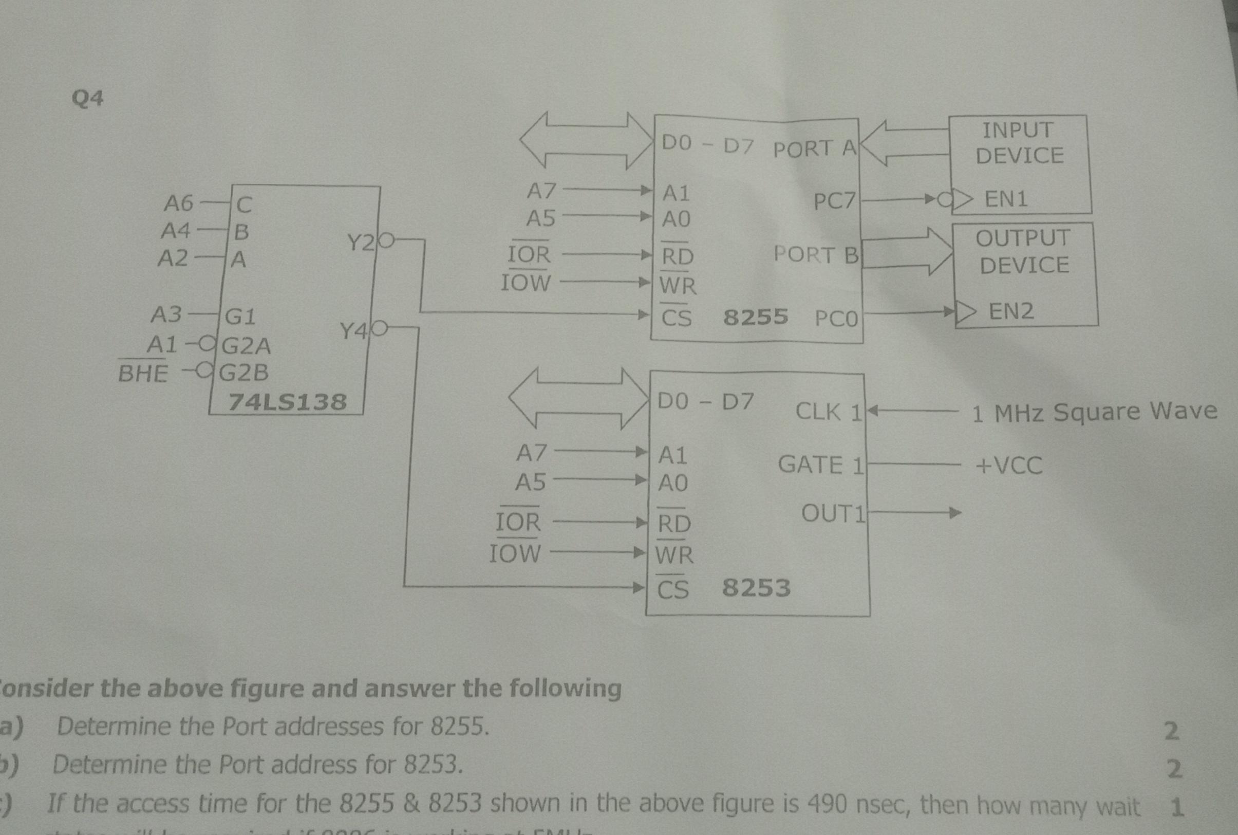
HOMEWORK (GOOD) What exactly will be A0 in this question?

Post image
11 Upvotes

So here is my logic: We need BHE(bar) to be 0 for the decoder to be ON(and thus we can write port address for 8255 as asked in (1)). Now, i think it is missing that D0-D7 of 8255 is connected to which bus lines on 8086(as we can see it is not specified), so there can be two cases, D0-D7 and D8-D15. But essentially BHE is used to enable D8-D15 here as we dont use memory bank, if D0-D7 is connected then A0 should be strictly zero(and then word transfer will take place), but if D8-D15 is connected A0 wont matter. So A0 will be dont care condition in my opinion, what actually will be A0?

r/ECE • • Dec 24 '25

HOMEWORK (GOOD) Cmos sizing question

6 Upvotes

I am pretty confused about sizing. Is there a chance that this question was solved incorrectly?

Because my logic would be: let’s start with the pull-up network, so the entire pull-up network must have the size 6W/L. Then the highest logic-effort paths would be either G–C–A or G–D–B or G or G–E–B. Now, whichever path we choose, all of them are in series. If I assign the resistance of a PMOS that has size 6W/L as Rp, then each transistor must have the resistance Rp/3.

If the resistance is divided by 3, then since resistance is inversely proportional to size, their sizes must be 3 × 6W/L, thus 18W/L each.

Then the last path is G to F, and we know that G now has the resistance Rp/3 because we set its size as 18W/L. Then the resistance of F would be 2Rp/3, so its size must be 6 × 3/2 = 9W/L.

The way it is worded is pretty strange as well. Why would W/L be 6? Don’t we usually say something like PMOS has size 2W/L and NMOS has size W/L? I find it strange that we are saying something like W/L = 6.

r/ECE • • Jan 30 '26

HOMEWORK (GOOD) Any Hardware engineers available for question?

5 Upvotes

Hi I'm looking to interview someone who does hardware engineering/design for a project I'm doing for school. It'll be a simple 8 question Q&A primarily based on your works experience in that field, so if anyone is willing to take the time to answer questions let me know as soon as possible please!

r/ECE • • Nov 04 '25

HOMEWORK (GOOD) what am i missing in the DC analysis of this NMOS circuit?

3 Upvotes

I have the following circuit:

I want to sketch the v_out vs v_in for v_in from 0-2V. I know that Vg2 = 618mV, and VCC=2V.

I start by checking M2 (as I have fewer variables with it). VGS2 = Vg2-0 = Vg2, I'm also given Vth2 = 444mV, so I get that VGS2 > VTH2, so the transistor is open, then to check sat/lin: VDSAT2 = VGS2 - VTH2 = 174mV and VDS2 = VOUT - 0 = VOUT.

so it's in sat when VOUT2 > 174mV, otherwise in saturation.

now i move to the top NMOS M1: checking when it's open: VGS1 = VIN - VOUT > VTH1, i dont know explicitly VTH1 as it involves the bulk effect.

Now to check the operation mode of M1: Assume sat.

VDS1 = VCC - VOUT = 2 - VOUT > VIN - VOUT - VTH1 = VGS1 - VTH1.

This simplifies to 2+VTH1>VIN, which is always true as VIN is less than 2, so M1 is in saturation.

This is what I know how to do, but I want to plot VOUT vs VIN. How do I do that? What steps am I missing? anything else?

I would really appreciate your help here.

btw, both lambda and gamma are non-zero here.