r/ECE • u/throwaway8490247 • 3d ago
HOMEWORK (GOOD) Help with Thevenin equivalent circuits
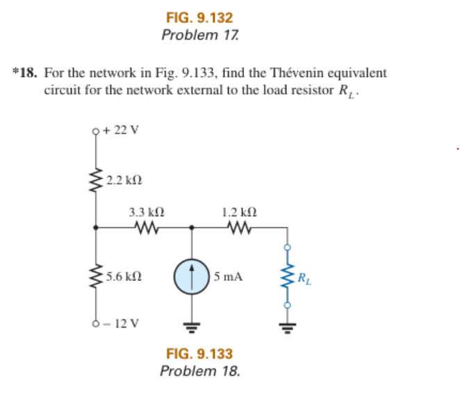
In advance, I appreciate the help. I know this sub has a "do your own homework" attitude, but I've been staring at this problem for hours and can't figure out how to proceed. I understand TEC circuits pretty well, and had minimal issues with every other problem, but this specific one has stumped me. I've reread my chapter and watched TEC lessons on Youtube, but can't find anything that fits this specific example.
I've got half of this solved. Finding the Thevenin Resistance is simple enough, I shorted the Voltage Sources and opened the Current Source. 1200 +3300 + ((2200*5600)/(2200+5600)) is ~6080 ohms.
Where I'm running into an issue is finding the Thevenin Voltage. If the Load Resistor is opened, then it seems to me that the entire circuit is open. If the circuit is open, then the current source has nowhere to flow, and I can't find the solution. I would convert the current source to a voltage source if I could, but I don't think that can be done, because there is no parallel resistor.
The best solution I've come up with is to find the voltage at the junction between the two voltage sources and their resistors, while treating the current source as non existent because it doesn't have anywhere to flow to. However when testing this result (12.41 V) in a simulator it doesn't seem to work. What am I doing wrong?
Edit: Solved, Thank you everyone for your help. If anyone is having trouble with a problem like this themselves, I worked it out and posted the steps in the comments below.
17
u/South-Mine7572 3d ago
If the load is open then all the current will flow through the 3.3k resistor find the voltage at the tip of the current source and since the 1.2k resistor is connected to open circuit and no current is flowing the voltage difference across it is zero meaning it has the same voltage on both terminals (the voltage of the other terminal of the current source) A KCL equation and KVL equation and your circuit is solved
5
u/throwaway8490247 3d ago
Thank you! This made it click for me. I think I had some kind of mental block because the current is flowing into a negative voltage source rather than ground. Obvious in hindsight lol
For anyone who may come across this in the future and is having trouble as well here is what I did;
I1 + I2 + I3 = 0 (V will stand in for the voltage at the junction between the 3 resistors)
(22-V)/2,200 + (-12-V)/5,600 + .005 = 0
(22-V)/2,200 + (-12-V)/5,600 + = -.005 | Bring the known current to the other side
(5,500)(22-V) + (2,200)(-12-V) = -.005(5,500)(2,200) | Multiply each side by (5,600)(2,200)
121,000 - 5,500V - 26,400 - 2,200V = -61,600 | Do the math
96,800 - 7,800V = -61,600 | Add like variables
-7,800V = -158,400 | Subtract 96,800 from both sides
V = ~20.308 | Divide each side by -7800
This is the voltage at the junction, now to get the voltage at the tip of the current source add the voltage drop across the 3.3k resistor (.005 * 3,300 = 16.5 V) so, 20.308 V + 16.5 = 36.808 V
Thevenin Voltage = 36.808 V
2
u/tombo12354 3d ago
To add to this, setting up two KCL loops, the voltage drop across the 3.3k resistor is apparent, as it's just the 5mA current source feeding it in that loop. But that's just the voltage drop across the resistor: to figure the voltage relative to ground, you need the voltage at the junction of the 2.2k, 3,3k, and 5.6k, which you can figure out from the other KCL loop.
Be careful with your signs (both voltage and current). I'd imagine that part of the intent of this problem, given two voltage sources of opposite polarities. While you only need to find the voltage once, you can check the voltage a the resistor node by calculating it off both voltage source. That should help with checking the polarities.
2
u/ee_control_z 3d ago
Just by looking at the figure, I already know its from Sedra.
1
u/throwaway8490247 1d ago
It's actually Boylestad. I've never used Sedra, but I really don't like this book. It's so hard to follow, and the example problems usually only get you halfway to the solution on the homework. I typically just read over the chapter to get the idea, then watch youtube lessons until the concept sticks.
1
u/ee_control_z 19h ago
Oh, ok. They must use the same circuit editor then because the circuit design art follows what is found in Sedra. ;)
1
u/PrestigiousAction694 3d ago
An alternative approach is that for an linear circuit, you can use superposition. First assume there are only two voltage sources (current source becomes open circuit) and calculate the open circuit voltage for the load. Then assume there is only the current source (both voltage sources are shorted to ground), calculate the open circuit voltage again. Then add the two parts together to get the final Thevenin voltage.
1
u/Chanesaw_tm 1d ago
if the load resistor is opened then it seems to me that the entire circuit is open
That isn't true. If you open RL then the current through the 1.2k resistor is zero but you can still have current through all other branches of the circuit.
Since the middle is a current source you know the current through the 3.3k resistor is 5mA and from there you solve for the unknown voltage at the three resistor intersection with Kirchoff laws.
Once you know that you take the 5mA current through the 3.3k resistor to get the voltage to the left of the 1.2k resistor. Once you know that you know the voltage on the right of the 1.2k resistor is the same, such that you have zero voltage across it for zero current.
•
u/DownloadableCheese 3d ago
I'd just like to thank OP for actually complying with Rule 1. You showed your work and have specific questions, rather than just whining about not understanding your homework.