r/ECE • u/NoObm_ster69koRg • Jul 08 '26
HOMEWORK (GOOD) Poles of this circuit?
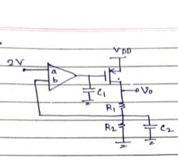
This is one of the questions my senior came across in his interview.
Question was to find the pole of the circuits. In the document, my senior has remarked apparently there are 2 poles, and even I seem to think this but not getting a concrete way to prove it.
Moreover he was also asked about the locations of the poles.
Now I beleive one of the pole is (-1/R2C2)?
But is that right? If yes I don't think at that frequency the Vo saturates(which I feel is the requirement for pole)
Overall any suggestions to better solve such questions.
Note: it's expected that the answer is more intuitive rather than rigourous KCL and KVL
Edit: forgot to mention. Circuit is in negative feedback as in b is positive terminal and a is negative terminal of the opamp
7
u/The-PhantomDeluxe Jul 08 '26
You can find poles witha simple trick with the formula of -1/ReqC Req is the resistance across the capacitor. I kind of forgot the whole thing but you can watch this video on how to find poles and zeros with intuition
2
1
u/NoObm_ster69koRg Jul 08 '26
Oh yeah himanshu is goated. But couldn't get much clarity from this video
2
u/davidsh_reddit Jul 08 '26
Aside from R2C2, there’s a pole defined by GBWP of opamp and C1/MOSFET capacitance.
1
u/NoObm_ster69koRg Jul 08 '26
So like the second pole comes into play if you consider the opamp as a first order low pass filter rather than an ideal pole right?
2
u/davidsh_reddit Jul 08 '26
In fact there’s 2 poles. 1 pole depends on gain of opamp and GBWP, other pole is from capacitor and exact frequency depends on the opamp design. If C1 is too large the double poles can make it potentially unstable
5
u/1wiseguy Jul 08 '26
I have a problem with C1.
It's not normal to put a capacitor on the output of an opamp. That would make some opamps unstable, so you would need more info about that particular opamp.
I would remove C1 and explain that it doesn't belong there.
1
u/NoObm_ster69koRg Jul 08 '26
Ok what about my estimation about one of the poles?
Is that correct?
And to your question about c1, will it become acceptable if say the opamp has finite output resistance?
3
u/Judaveschla Jul 08 '26
C1 and C2 are compensation capacitors. They are added to force the system into a single pole system.
The actual intrinsic poles are two:
At the output of the amplifier, which is dependent of the amplifier topology. But let say it is (1/gm)(Cgd).
At the output of the regulator, the pmos pass device which has a parasitic Cdd = Cgd + Cds. Your V0 node.
C1 will add a zero to cancel one of the intrinsic poles. And C2 adds another pole probably with the aim to stabilize or make the output dominant.
This analysis is for somewhat advance analog design, so I am not going to go further than that.
2
u/flextendo Jul 08 '26
thats 100% not a zero. Its a dominant pole compensation (if we assume the amplifier is an OTA) and C2 is a lot smaller (also no significant cap on Vo). You are correct that it should be connected to Vdd though
2
u/Judaveschla Jul 08 '26
You are correct the ESR analysis is for an output V0 capacitor not present in this problem.
And C1 is NOT a zero it's a pole introduced into the system, the series resistance (sometimes a variable resistor...fet device) is to track the zero-pole cancellation that happens while changing the load of the LDO.
But I think is beyond OP question. So I will leave like that.
Thanks for the correction!
1
u/Judaveschla Jul 08 '26
Wrong.
C1 is a compensation capacitor for stability, which add a zero into the system to cancel the pole at the output of the amplifier. This makes the external pole of this LDO, the dominant pole, which will behave as a single pole system.
The only issue I see is that C1 typically should be tied to VDD instead of ground for a pmos pass device.
3
u/LevelHelicopter9420 Jul 08 '26
C1 does not add a zero to the open loop gain…
0
u/Judaveschla Jul 08 '26
C1 has equivalent series resistance (ESR) which add a zero. The correct implementation is to add a series resistance to C1 and not to rely of the variable and unknown ESR value of the capacitor.
But yeah, C1 in series with ESR forms a zero into the system.
3
u/LevelHelicopter9420 Jul 08 '26
You’re assuming that ESR will have a significant value to even matter. It does not work that way! Also, the ESR would be in series with the output impedance of the OTA, which effects pole position.
1
u/Judaveschla Jul 08 '26
Agreed, thanks for the correction, I added an explanation to other user down below!
Thanks again!
1
u/LevelHelicopter9420 Jul 08 '26
The lead compensator, you are talking about, does exist. But it is usually employed in the last stage of an OTA, not between gain stages!
2
u/davidsh_reddit Jul 08 '26
If what is shown is an opamp, this is a pole. I find it ambiguous though, could be some other kind of amplifier too since there’s no feedback and no + and - on inputs
0
u/1wiseguy Jul 08 '26
Where did that knowledge come from? Can you cite a reference?
I have never seen a circuit that deliberately connects a cap to an opamp output. There are opamps that are specified to drive capacitive loads (e.g. coax cable capacitance), and there are tricks to make a general purpose opamp stable when driving a capacitance, but I never heard of using a cap on an opamp output to create a zero, or any other function.
How would you calculate the cap value? Does that assume the opamp has a known output resistance? That's not generally specified.
1
u/Judaveschla Jul 08 '26
This particular setup is used in Low Dropout Regulators (LDO) and for C1 that particular compensation is called "stub compensation", there is other types of compensation like Miller compensation that accomplishes similar results.
1
u/1wiseguy Jul 08 '26
Is that something that would be implemented within a silicon chip design? Would the amplifier be specifically designed with the right output impedance to make that work?
It seems squirrelly to do that at the board level, where you would depend on an unspecified opamp parameter.
1
u/Judaveschla Jul 08 '26 edited Jul 08 '26
That is correct this is done on integrated circuits, internally.
Although, sometimes, for example on LDOs, the output dominant pole capacitor can be huge and needs to be added at the PCB level. So you can see TI datasheets (for example) asking you to add a big capacitor at the output of the regulator to ensure the single pole system.
1
u/1wiseguy Jul 08 '26
The output cap for an LDO is critical, because the power stage works like a current source, and the output cap impedance directly defines the loop gain. So there are specific requirements for the cap value and ESR.
For an old school regulator like a 7805, the power stage pretty much works like a voltage follower, which has a low output impedance, so the cap does not have a lot of impact on the loop gain. So there are no rules for that output cap. It will be stable with a small ceramic, a big electrolytic, or no cap at all.
But C1 in that circuit is not an output cap.
1
u/Judaveschla Jul 08 '26
That is correct, for the output or load cap.
For C1 going back to your original question is a compensation cap that is added internally or integrated. So on PCB level you are not going to interact with C1.
1
u/OhmmOhmmOhmm Jul 08 '26
My guess is pole 2 is the rc formed by c1 and the pmos conducting resistance.
That or the natural cut-off from the op amp itself.
1
u/NoObm_ster69koRg Jul 08 '26
I see. What about the pole that I told about. Is that correct?
3
u/OhmmOhmmOhmm Jul 08 '26
I would think so. Ngl, I forgot when I pole is a pole, and a zero is a zero.
But I think low-pass filters act as poles, so i would assume they are all correct.
1
1
1
1
u/God_Phoenix3381 Jul 09 '26
Btw is it 2V or 2u(t)?
1
1
u/cinisoot Jul 10 '26
OP, I want to clarify this point: the existence of C1 does contribute a zero to the transfer function. The proof is in this paper by Prof. Ali Hajimiri. The result is stated in Section VI (A), "Number of Poles and Zeros."
In other words, the number of zeros in the circuit is equal to the maximum number of energy-storing elements that can be simultaneously infinite-valued while producing a nonzero transfer constant from the input to the output.
In fact, assuming that we are looking at the transfer function H = vo/vdd, both C1 and C2 introduce zeros.
You can read the cited reference for the full details, but in summary: just like how in the method of open-circuit (or zero-value) time-constants a zero-valued capacitor is an open circuit, an infinite-valued capacitor is a short circuit. Therefore, for the given transfer function H, we find the maximum number of capacitors N that we can short circuit and still have a nonzero transfer function. This number N is equal to the number of zeros in H.
Here is the equivalent circuit when C1 and C2 are both infinite-valued, i.e., both are short circuited. As you can see, vo/vdd is clearly not zero, and so we have two zeros.

If you want to explicitly prove this, here's some Matlab code you can use to find the two zeros. This assumes that M1 has some gm1 and the amplifier has a gm2 with finite output resistance ro. The zeros are at z1 = -1/(C1*ro), and z2 = -1/(C2*Req), where Req = R1||R2.
1
24
u/adithya_t Jul 08 '26 edited Jul 08 '26
First you tell the interviewer there are 2 poles due to c1 and c2. Then you ask them which one is larger. The larger capacitor gives the smaller pole and pole due to that comes first, so smaller cap is opened and we check effective resistance across the larger cap and pole is -1/Reff×Clarge. Then for second pole you short the previous cap and find Reff across the other cap and use the same formula